Multiplexed Signal Generator with Mixer (axis_sg_mixmux8_v1) - QICK Firmware
axis_sg_mixmux8_v1 is an 8-tone multiplexed (muxed) signal generator,
almost identical in its control logic to Signal Generator Mux8 (axis_sg_mux8_v1) - QICK Firmware
(axis_sg_mux8_v1), but with a complex (I/Q) datapath so that its
output can drive the RFDC’s own digital mixer/NCO. The module lives under
firmware/ip/axis_sg_mixmux8_v1/ and is exposed to Python through
qick.drivers.generator.AxisSgMixMux8V1.
1. General Description
Like axis_sg_mux8_v1, this block plays up to 8 independent, phase-coherent
CW tones simultaneously: each tone has its own frequency (PINCx_REG),
phase (POFFx_REG) and gain (GAINx_REG), and the tProcessor selects
which subset of the 8 tones is active for a given pulse via an 8-bit mask
and a sample count, pushed onto s_axis (see Section 3.2 below). The
8 (masked) tones are summed together and streamed out at up to N_DDS
samples per clock.
The one substantive RTL difference from axis_sg_mux8_v1 – confirmed by
diffing the two IPs’ src/ directories file-by-file (diff -rq
firmware/ip/axis_sg_mux8_v1/src firmware/ip/axis_sg_mixmux8_v1/src) – is
that every per-tone DDS core is configured as a complex (I/Q) oscillator
instead of a real-valued one, and the entire summation/quantization
datapath downstream of it is duplicated to carry both components. Concretely:
In
dds_top.v’sdds_compiler_0(the Xilinx DDS Compiler core), theOutput_Selectionparameter is"Sine"inaxis_sg_mux8_v1(a real-valued 16-bit output) versus"Sine_and_Cosine"inaxis_sg_mixmux8_v1(a packed 32-bit{cosine, sine}output). This is the actual source of the “mix” in the name.dds_dout_o, the DDS-to-gain-stage bus, isN_DDS*16bits wide inaxis_sg_mux8_v1andN_DDS*32bits wide inaxis_sg_mixmux8_v1(16-bit real vs. 16-bit-I + 16-bit-Q per DDS lane).The per-tone gain multiply in
dds_top.v(prod_a_real = dds_dout_la[i]in mux8 vs.prod_a_real = dds_dout_la[i][15:0]/prod_a_imag = dds_dout_la[i][31:16]in mixmux8) is duplicated: the same signed 16-bitGAIN_REGvalue is multiplied independently against the real and imaginary DDS samples. This is a real (scalar) amplitude scale of a complex sample, not a complex/quadrature multiply – there is no cross term (noI*sin(LO) - Q*cos(LO)-style rotation) anywhere in this IP’s RTL.In
sg_mux8.v, the 8-tone masking, the 7-stage pairwise adder tree that sums the (up to 8) active tones per DDS lane, and the mask-popcount-based output quantization (see Section 3.3) are all bit-for-bit the same logic asaxis_sg_mux8_v1’s – just instantiated twice, once for the real (I) rail and once for the imaginary (Q) rail, in parallel.m_axis_tdata_oends upN_DDS*32bits wide (16-bit I + 16-bit Q per DDS lane) instead ofaxis_sg_mux8_v1’sN_DDS*16bits (real only).axi_slv.v(the AXI-Lite register file),ctrl.sv(the FIFO-drain / mask / enable FSM),phase_ctrl.sv(the phase accumulator, including its use ofmult_32x32.v),latency_reg.vandsynchronizer_n.vhdare byte-identical files between the two IPs (confirmed bydiff -rqreporting no difference for any of them). There is no additional register, FSM, or signal path in this IP’s own RTL for an internal mixer – noMIXFREQ-style register, no second NCO, no per-lane local oscillator anywhere inaxis_sg_mixmux8_v1’s source.
So where is the “mixer”? It is the RFDC’s (RF Data Converter) own digital
mixer/NCO on the DAC tile, external to this IP – axis_sg_mixmux8_v1
simply produces the complex (I/Q) samples that RFDC mixer needs as input.
This is corroborated by the Python driver (qick_lib/qick/drivers/generator.py):
AxisSgMux8V1’s docstring: “AXIS Signal Generator with 8 muxed outputs, fullspeed (**no DAC mixer*).”* versusAxisSgMixMux8V1’s: “AXIS Signal Generator with 8 muxed outputs, **using DAC mixer*.”*AbsSignalGen.set_mixer_freq()/get_mixer_freq()(the methods that back this behavior for everyHAS_MIXER=Truegenerator, including this one) call straight through toself.rf.set_mixer_freq(self['dac'], f, ...)– i.e. they configure the RFDC block driver, not any register insideaxis_sg_mixmux8_v1itself.AxisConstantIQ(anotherHAS_MIXER=Truegenerator) states the same architecture explicitly: “Plays a constant IQ value, which gets mixed with the DAC’s built-in oscillator.”
Because the mixer frequency is a single value set on the DAC tile
(set_mixer_freq(ch, f) takes one f for the whole generator channel,
and QickConfig.calc_muxgen_regs() computes every tone’s PINC as
f_dds = freq - mixer_freq relative to that one value), the local
oscillator is shared across all 8 muxed tones on a channel, not independent
per tone/lane. The 8 tones are combined digitally at baseband (each
keeping its own PINC/POFF/GAIN relative to that shared center
frequency) and the RFDC mixer then shifts the entire already-summed comb
up (or down) in frequency, which is what lets axis_sg_mixmux8_v1
(unlike axis_sg_mux8_v1) place its whole multi-tone output away from DC,
including outside the DAC’s first Nyquist zone.
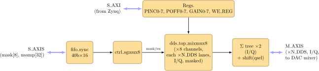
Top-level block diagram – identical control/FIFO structure to
axis_sg_mux8_v1, but each dds_top_mixmux8 tone slot is a
complex (I/Q) oscillator and the adder tree is duplicated for both
rails. M_AXIS carries the already-summed I/Q comb to the RFDC’s
own mixer on the DAC tile – there is no mixer inside this IP.
Note
This page documents only axis_sg_mixmux8_v1’s own RTL and driver.
The RFDC mixer/NCO itself (register layout, valid frequency ranges,
Nyquist-zone handling) lives in AMD’s RF Data Converter IP and the
qick.qick.AxisRFDC-family driver, not in this IP – see
How to ensure frequency matching for the software-level picture of how
generator and readout frequencies are kept consistent.
2. Synthesis Parameters
Parameter |
RTL Default |
Description |
|---|---|---|
|
2 |
Number of parallel DDS/output lanes (samples produced per clock on
|
There is no synthesis parameter that changes the mixer/complex behavior –
that is hard-wired into the dds_compiler_0 IP core configuration
(Output_Selection = "Sine_and_Cosine"), unlike ENVELOPE_TYPE or
GEN_DDS on the arbitrary-waveform generators (Signal Generator v6 (SG-v6) - QICK Firmware).
3. Datapath
3.1 Top-level structure
axis_sg_mixmux8_v1.v instantiates exactly two blocks (this wiring is
identical in shape to axis_sg_mux8_v1.v, differing only in the
m_axis_tdata bus width):
axi_slv– the AXI-Lite register file (Section 4).sg_mux8– the FIFO, control FSM, 8 DDS/gain stages, adder tree and quantizer (Sections 3.2-3.3).
3.2 Waveform trigger FIFO and control FSM
The tProcessor triggers playback by pushing a 40-bit descriptor onto
s_axis_tdata_i (via a 16-deep FIFO, fifo_wr_en = s_axis_tvalid_i):
Field |
Bits |
Description |
|---|---|---|
|
|
One bit per tone (bit i enables tone i’s |
|
|
Number of output samples (cycles) to play before returning to idle. |
ctrl.sv is a small FSM (READ_ST -> CNT0_ST -> CNT_ST -> READ_ST)
that drains this FIFO one descriptor at a time, latches mask/nsamp,
asserts the shared output-enable (en_o, latency-matched to the datapath
via a latency_reg) for nsamp cycles, and holds mask_o for the
duration. This file is byte-identical between axis_sg_mux8_v1 and
axis_sg_mixmux8_v1.
3.3 Per-tone DDS, gain, and the adder/quantizer tree
sg_mux8.v instantiates 8 dds_top blocks (one per tone), each driven
by that tone’s PINCx_REG/POFFx_REG/GAINx_REG. Inside
dds_top.v:
phase_ctrlcomputesN_DDSparallel, phase-coherent phase/PINC words (usingmult_32x32for thePINC*N_DDSandPINC*sample_countproducts needed to keep theN_DDSlanes phase-coherent), latched on a rising edge of the (resynchronized)WE_REG.Each lane’s
dds_compiler_0produces one DDS sample per clock – real-only (Sine) inaxis_sg_mux8_v1, complex I/Q (Sine_and_Cosine) inaxis_sg_mixmux8_v1.The (real, or real+imag) DDS sample(s) are scaled by that tone’s signed 16-bit
GAIN_REG(prod_real = I*gain, and in mixmux8 alsoprod_imag = Q*gain), each independently rounded back down to 16 bits.
Back in sg_mux8.v, for each DDS lane the (up to 8) tones selected by
mask are summed via a 7-stage pairwise binary adder tree
(add0..add7 -> sum0..sum3 -> sum4..sum5 -> sum6), growing from 16 to 19
signed bits to avoid overflow, then quantized back down based on
qsel = popcount(mask) (the number of simultaneously active tones):
|
Shift |
Bits taken from the 19-bit |
|---|---|---|
1 |
none |
|
2 |
|
|
3 or 4 |
|
|
5, 6, 7 or 8 |
|
|
This scaling (average rather than a raw sum) is applied identically and
independently to the real and imaginary sums in axis_sg_mixmux8_v1; in
axis_sg_mux8_v1 it is applied only to the single real sum. The final
per-DDS-lane output word on m_axis_tdata_o is
{dout_imag[i], dout_real[i]} (32 bits: Q in the high 16 bits, I in the
low 16) in axis_sg_mixmux8_v1, versus just dout_real[i] (16 bits) in
axis_sg_mux8_v1.
4. Register Map
The AXI-Lite register file (axi_slv.v, byte-identical to
axis_sg_mux8_v1’s) is a flat array of 32-bit words, word-addressed from
s_axi_awaddr[7:2]. Verified directly from the RTL’s address-decode
case statement and its register->port assign list at the bottom of
axi_slv.v:
Register |
Byte address |
Width |
Description |
|---|---|---|---|
|
|
32 bits |
DDS frequency tuning word for tone 0..7 ( |
|
|
32 bits |
DDS phase offset for tone 0..7 ( |
|
|
32 bits (AXI word); only bits [15:0] reach the hardware |
Signed gain for tone 0..7. The AXI-Lite word is 32 bits wide, but in
both |
|
|
1 bit (bit 0 of the word; pulse) |
Write-enable strobe. A 0->1 transition (resynchronized per-DDS by
|
This matches, word for word, the register map that
AbsMuxSignalGen._init_config() builds programmatically in the Python
driver (pinc0..7_reg at word indices 0-7, poff0..7_reg at 8-15,
gain0..7_reg at 16-23, we_reg at 24) – no discrepancy was found
between the RTL address decode and the driver’s register offsets.
5. Python Interface
AxisSgMixMux8V1 (qick_lib/qick/drivers/generator.py) is a thin
subclass of AbsMuxSignalGen (shared with AxisSgMux8V1 and the other
muxed generators) that only sets the class attributes describing this IP’s
capabilities:
class AxisSgMixMux8V1(AbsMuxSignalGen):
    bindto = ['user.org:user:axis_sg_mixmux8_v1:1.0',
              'QICK:QICK:axis_sg_mixmux8_v1:1.0']
    HAS_MIXER = True
    B_DDS = 32
    N_TONES = 8
    HAS_GAIN = True
    HAS_PHASE = True
    B_PHASE = 32
The only difference from AxisSgMux8V1’s class attributes is
HAS_MIXER = True (vs. False) – everything else (tone count,
frequency/phase/gain widths) is the same.
As with the other pulsed generators, most QICK programs never call the
low-level register-setting methods directly – they configure this
generator through QickProgram.declare_gen() and then play tones by
selecting a subset of them with mask:
from qick import *

soc = QickSoc()
prog = QickProgram(soc)   # or QickProgramV2, depending on tProc version

# gen_ch 0 is bound to an axis_sg_mixmux8_v1 instance in this example.
# Because HAS_MIXER=True, a mixer_freq is required; it sets the RFDC's
# NCO, shared by all 8 tones on this channel.
prog.declare_gen(
    ch=0,
    nqz=1,
    mixer_freq=500.0,                  # MHz, shared LO for all 8 tones
    mux_freqs=[-50.0, 0.0, 75.0],       # MHz, offsets from mixer_freq
    mux_gains=[0.9, 1.0, 0.5],
    mux_phases=[0, 0, 90],
    ro_ch=0,                            # frequency-match to readout 0
)

# Play tones 0 and 2 (mask selects which declared tones sum together)
prog.pulse(ch=0, style='const', mask=[0, 2], length=1000)
Directly poking registers (set_tones()/set_tones_int() on the
driver, reached as soc.gens[0]) is supported for debugging but is not
the normal path – see AbsMuxSignalGen.set_tones()’s docstring: “This
method is not normally used, it’s only for debugging and testing.” Setting
the mixer frequency directly (soc.gens[0].set_mixer_freq(f)) is likewise
meant for constant-IQ-style outputs; for tProc-controlled generators like
this one, QickProgram.config_gens() calls it for you from the
mixer_freq passed to declare_gen().